Australian Bell uses the best technologies available to expand the possibilities for the design of bells, tuned percussion instruments and musical sculptures.
COMPUTER MODELING OF VIBRATION AND SHAPE OPTIMISATION
|
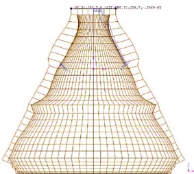
A complex bell profile produced by the method described above using the Reshape program.
The grid of lines shows the elements that the model was divided into (the mesh). The smaller blue profile was the starting profile for this stage of the design (drawn at a different scale). Note the absence of the notch on the inside wall which was added by the computer in this design phase. Note also the complex shape of the foot of the bell. |
Three dimensional, flexural vibrations of solid objects can be computer modeled using a technique called Finite Element Analysis (FEA). This technique breaks up a 3D object into many small parts of simple shapes. The elastic flexing of each part can be described by a simple equation (given the shape and material properties such as density and elasticity) and the contribution of all the parts is then summed. When modeling vibration it is important to include in the model (or at least take account of) how the object is suspended or attached to a support.
Shape optimisation is a more recent technology in which the computer calculates changes to the shape of a model based on a series of FEA analyses and some design objectives. Australian Bell uses a technique known as gradient method optimisation, in which the computer analyses the direction and amount of change in the design variables due to a series of shape changes, and then calculates the direction and degree of the next shape change. A variety of design targets and constraints may be applied to the task, such as, which overtone should change and which should remain unchanged, which parts of the model should be allowed to move and in which directions, and which parts should move in unison.
SOUND TRANSMISSION
A different type of computer modeling may be applied to describing how sound is reflected and diffracted by the architecture surrounding a sound source and listener. These techniques treat sound as if it was a light ray reflecting off multiple surfaces and diffracting about edges. Once all the possible reflection paths including sound absorption, diffussion and diffraction have been calculated, the effect at a listening position over the length of time required for all the reflections to arrive can be detirmined. Sound transmission effects can make a great difference to the enjoyment of music, the intelligibility of speech and to general noise levels.
Once all the spatial effects on sound transmission have been calculated it is possible to convolve (cross multiply) an anechoic recording with these files to produce a spatial rendering of the sound played over a speaker array or through headphones. The application of these technologies is being investigated to enable remote listeners to hear the Federation Bells spatially reproduced across the internet.
Prediction of sound transmission and radiation is more difficult when the wavelength of the sound in air is close to the physical dimensions of the architectural space being represented. Finite element modelling approaches similar to those used to model the bells are being investigated to handle these types of problems.
|
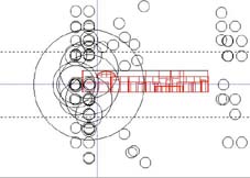
Room acoustic modeling calculates virtual sound sources (like reflected images in a mirror). This image shows the virtual sources about a listening position. The larger the circle, the louder the perceived source at its centre. The further the virtual source is from the listening position the longer the sound takes to arrive. |
HUMAN HEARING
The human ear is a very complex organ which perceives with only about 3,600 sensing cells in each ear, but with millions of neural connections to process the sound. The frequency range of human hearing is from 20 Hz to about 16,000 Hz, and groups of about 150 sensing cells will respond to any sound within a frequency band (critical bandwidth) which is about 100 Hz at low frequencies and over 1000 Hz at high frequencies. Within this band all the sensing cells are excited at once and so it is very possible that individual frequencies will be obscured (masked) by other sound signals in the same frequency band. This means that parts of a bell's spectrum will obscure other parts (usually lower frequency components masking higher frequency components) which has important implications for the perception of pitch.
Australian Bell has used computer models of hearing based on calculating masking patterns to detirmine the various pitch percepts arising from enharmonic bell sounds. This modeling enabled bells with 2 and even 3 pitch percepts of almost equal strength to be designed. These bells have been called polytonal bells.
 |
|
A JAPANESE BELL AT NISO-IN TEMPLE IN KYOTO
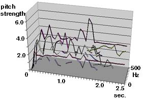
This image is a graph of the pitch strength calculated for a Japanese temple bell.There are 3 pitch percepts that last for the first 2.5 seconds. Note how the strength of pitch varies as the amplitudes of various partial frequencies fluctuate and decay.
The high frequency percept is due to a single loud partial. The sharp peak at about 1.5 seconds is due to the decay of lower frequency partials that were partialy masking this tone at the time when it was beating loudly. The mid-frequency percept increases in strength as some partials decay. |
AURALISATION
Given the complexity of human hearing and sound in musical contexts it is often an advantage to acoustically simulate the desired design outcomes. The sound of bells designed using FEA and shape optimisation has been simulated by recording the spectra (using a Fast Furier Transform or FFT program) of an existing similar bell, altering the frequency and amplitude of certain partials through a graphic interface, and then resynthesising the sound by an inverse FFT. This was acheived using a program called Lemur after some modifications by its author.
 |
 |
 |
Japanese bell from Jorenge Temple, Kyoto |
|
|
|
|
Auralisation of the sound transmission characteristics of an architectural space is also possible. The sound arrival data at a listening position (impulse response) calculated by a computer model can be cross-multiplied (convolved) with a source recording to give the recording the spatial characteristics represented in the computer model.
CASTING TECHNIQUES
Casting methods have advanced dramatically over the last century. Once the bell has been designed, the task is to accurately translate the computer model into a cast bronze bell. The profiles are lasercut into strickle-boards, which are then fitted to a carefully engineered turntable. The strickle boards 'strike' or turn the inside and outside shapes of the bell in resin sand. This outer and inner mould is assembled together to leave a negative space which reflects the form of the computer model with allowances for shrinkage as the bell cools. Molten bronze is poured into the mould and after it has cooled the bell is removed from the mould with its tuning fixed in its form. Since Australian Bell has developed a wide range of bell tunings, our bells can have extremely complex shapes that could not easily be achieved using the various conventional bell-casting processes. The accuracy of our modern casting materials and technology is much greater than achieved by any bellfoundry before us.
Australian Bell chooses bronze alloys to suit the particular timbrel and tuning qualities we require of the bell being cast. Sometimes this requires the use of traditional bell metals or other times modern bronze alloys such as silicon bronze.
|
|
|
|
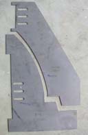
Lasercut steel patterns |
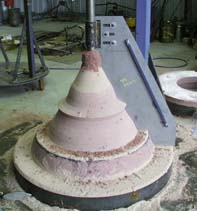
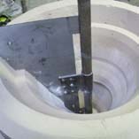
Using turntables to accurately turn the inside and outside mould shapes in sand mixed with a modern resin. The resin sets within an hour to produce a hard, stable mould free of moisture. |
Outside mould sections are assembled over the inside core. |
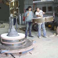
Bronze is poured from the furnace into a ladel before being poured into the mould. |
MACHINING
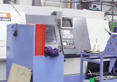
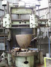
The complex profiles generated by computerised shape optimisation are either laser cut into steel plates to enable casting moulds to be made for larger bells, or are machined to very high tolerances on numerically controlled lathes for smaller bells. The pitch sensitivity of the human ear is such that differences in wall thicknesses of just 50 microns (millionths of a meter) can be detected in small bells. Australian Bell's harmonic bell profiles are detailed in computer models to 10 micron tolerances which can be repetatively produced on CNC lathes (shown below). Bells of larger diameters than 400mm often require fine tuning after they are cast. This is carried out on a large manually operated vertical lathe. The parts of the bell to cut are calculated by computer modelling.
|
Computer numerically controlled lathe for machining bells less than 400mm dia. at Harrops Engineering, Melbourne Australia |
|
Australian Bell's vertical lathe for machining bells of up to 1.5 meter diameter and 1.5 meter hight, located at Auscut Engineering, Kyneton Australia. |
|

.jpg)